Wednesday 29 October 2014

Mesh Construction


Primitives
A geometric primitive is a basic building block of 3D geometry such as a cube, sphere or cylinder.

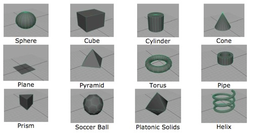
These are pre-built shapes available to 3D modellers that are used to save time and make great starting points for a variety of more complex models. The properties of primitives can often be easily changed to add subdivisions or to change the look of the shape eg. more coils in a helix.
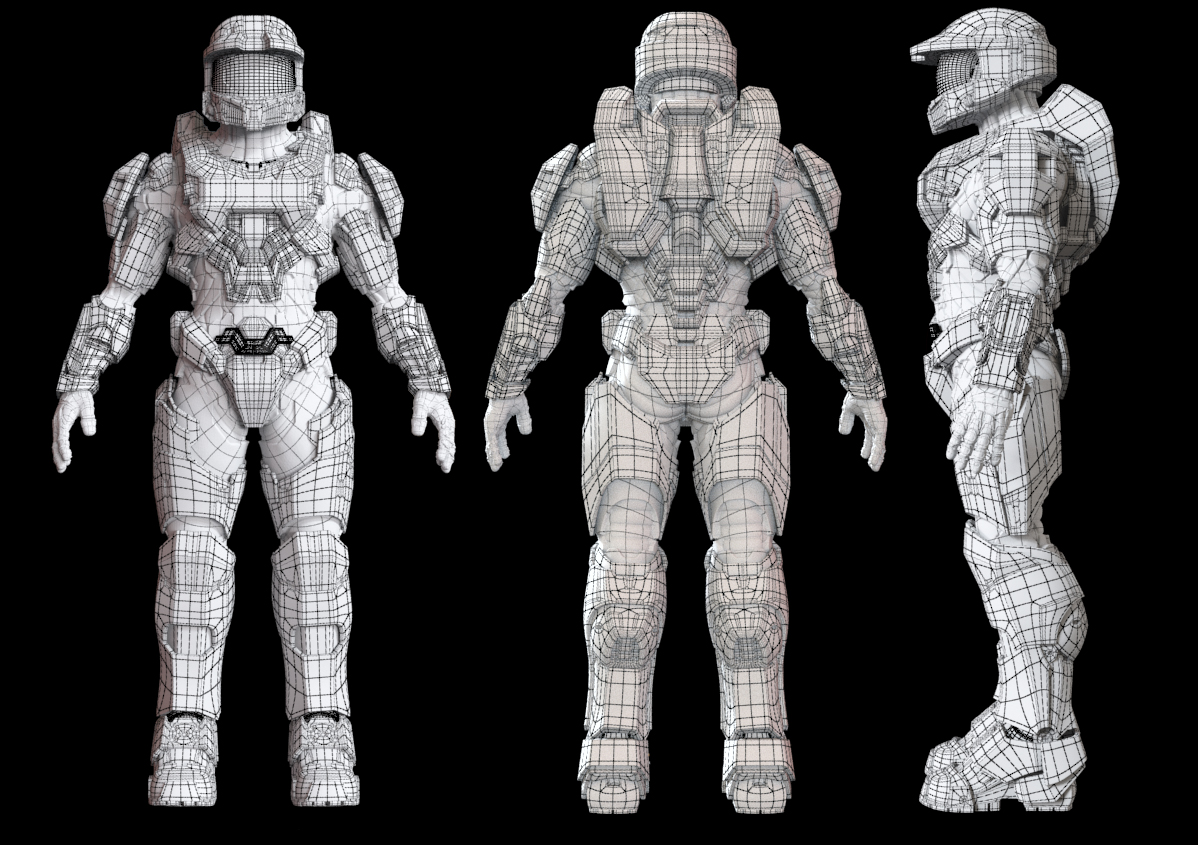
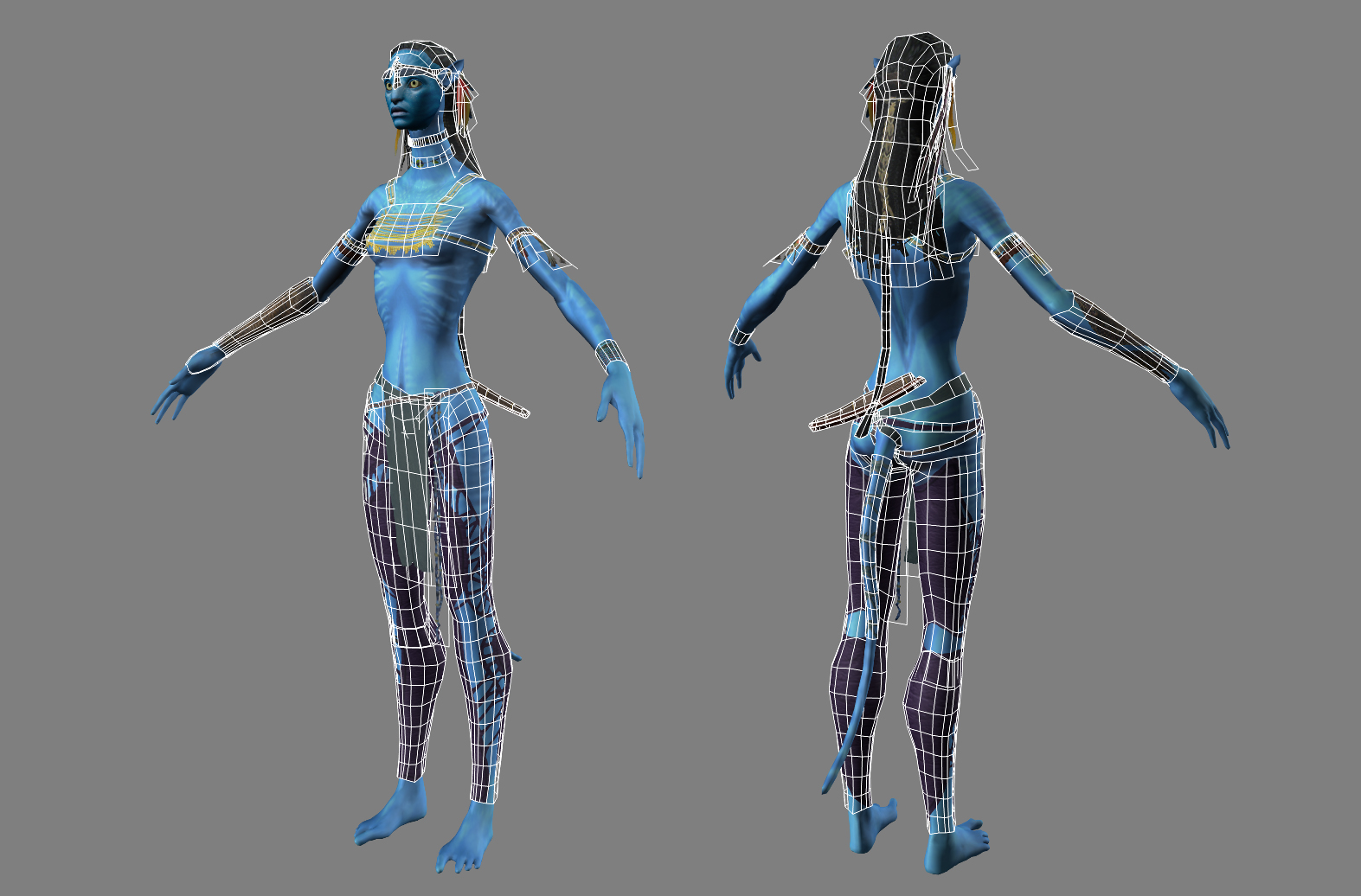
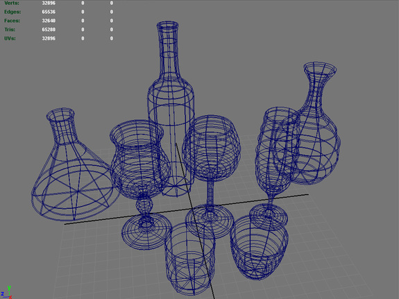
Primitives can be used effectively to create detailed looking assets such as in these examples.

Primitives are often used as the starting point for more advanced modelling techniques such as box or extrusion modelling.

Box modelling
This is a techniques for creating polygonal models in which the artist begins with a 3D primitive (often a cube - hence the name box modelling) and then refines the shape of this until the desired shape has been created.


This example demonstrates the box modelling process. You can see that the mesh began as a low resolution sphere which has been shaped and then subdivided (new edges added) at each stage to create the head you can see at the end.


Extrusion modelling
Extrusion modelling also tends to start with a primitive such as a cube but rather than adding subdivisions as is done with box modelling, new geometry is created with each extrusion.
In this example you can see the two main ways that extrusion can be used on faces. One face had been pushed in to create the door and another has been pulled out to create the chimney.

The two approaches aren’t mutually exclusive and in most cases these techniques need to be used together in order to create a complex model.

There is a range of other methods of creating 3D meshes worth investigating. These include;
  • Edge/contour modelling
  • NURBS modelling
  • Digital sculpting
  • Procedural modelling
  • Image based modelling
  • 3D scanning

Wednesday 22 October 2014

Geometric Theory for 3D Graphics


What is a 3D model?
A 3D model is a mathematical representation of a shape in 3D space. Cubes, spheres and cylinders are all examples of basic 3D models but they can also be very complex as you can see in these examples;

There are two main types of 3D models in use in the film and games industries these are NURBS surfaces and polygonal models. We’re mostly going to focus on polygonal models but I will give a quick explanation of NURBS surface modelling.

NURBS surfaces
A NURBS (Non-uniform rational B-spline) surface is a model created through the use of bezier curves (like the ones use to create vector graphics). To forms a NURBS surface the software interpolates between two or more curves and creates a smooth face to fill the space. Models constructed using NURBS are very mathematically accurate and are commonly used when modelling for engineering and automotive design.

Polygonal models
These types of models are more common in the film, animations and games industries and it’s these that we’ll focus on for the rest of this handout. Polygonal models are made up of vertices, edges and faces.

Vertices
These are points in 3D space. Each of these points is known a a vertex. Each vertex has its own coordinate information (x, y, z) and moving these vertices is a common method of shaping models. Here you can see vertices highlighted.

Edges
Edges are used to join vertices together. This creates a wireframe like the one here.

Faces
The thing that defines polygonal modelling is that the meshes are faceted. That means that they are made up of faces. Faces are used to fill the space between vertices and edges. In efficient modelling these faces are three or four sided (modelling in tris or quads). The faces that make up a 3D model is known as a mesh. The number of faces in a mesh is known as the poly-count and the polygon density is referred to as the resolution.
3D coordinate space and axes
The 3 dimensional space that games and applications such as Maya rely on is based on the Cartesian coordinate system. This is like a map for defining the position of points in 3d space. The system was developed by French brainbox Rene Descartes. Using this system space is defined using 3 axes, known as x, y and z. These represent the width, height and depth respectively. The coordinates for a point are written numerically in the order of x, y and z and look like this - (2,4,1).

The zero point of the axes is called the origin (0,0,0). This is where each of the three axes intersect. Heres an example of how this coordinate system looks and works.